
English 

Views: 0 Author: Site Editor Publish Time: 2026-09-01 Origin: Site


The bailey bridge carries a unique dual identity in the engineering world. It stands as a critical piece of World War II history. Simultaneously, it serves as the foundational standard for modern modular engineering. Donald Bailey invented this clever system in 1941. He designed it to solve severe rapid deployment bottlenecks during wartime. Today, project managers face very similar constraints. They must deploy emergency infrastructure rapidly across difficult terrain.
Understanding this historical design intent is your first crucial step. It helps in evaluating modern modular steel bridges properly. We will explore how these historical roots inform today's commercial choices. You will learn to select the right systems for temporary or permanent infrastructure. By grasping the core mechanics, you can make better procurement decisions.
Historical Foundation: The original 1941 design revolutionized structural engineering by prioritizing modularity, standardization, and manual assembly.
Core Component: The standard Bailey Bridge Panel remains the foundational building block, driving low-logistics deployment today.
Modern Evaluation: Current procurement heavily relies on selecting between evolved variants, specifically evaluating the SJ-321 Bailey Bridge and SJ-200 Bailey Bridge based on load capacity and span requirements.
Implementation Focus: Historical principles still dictate modern rollout realities—site prep, soil bearing capacity, and assembly-line launches remain critical to project success.
In World War II, military forces faced a severe logistical bottleneck. Existing bridges across Europe could not support new military equipment. Vehicles like the new Churchill heavy tanks weighed over 40 tons. Older stone and timber bridges collapsed under this immense pressure. Furthermore, traditional bridge construction was incredibly slow. It required heavy machinery. Armies moving quickly could not wait weeks for engineers to pour concrete.
Donald Bailey recognized this massive structural gap. He introduced a brilliant concept to the British War Office. He envisioned a pre-fabricated truss bridge made of high-tensile steel components. His design required parts small enough for standard military trucks to carry. More importantly, soldiers could lift every single piece by hand. This eliminated the need for heavy cranes in combat zones. Six men could easily carry the heaviest individual part.
The outcome of this innovation proved staggering. Allied forces built thousands of these structures across Europe. You can see their strategic success during the Italian campaign. They also secured vital supply lines immediately after the Normandy landings. We view this widespread use purely as evidence of the design's extreme reliability. It showcased unparalleled scalability. The system proved incredibly easy to deploy under high-stress conditions.
We must break down the fundamental architecture of the bridge to understand its longevity. The historical design translates directly into modern commercial advantages. The secret lies in strict modularity. It relies on standardized geometric forces. Tension runs through the bottom structural members. Compression pushes against the top members. Diagonal braces handle the shear forces efficiently.
The Bailey Bridge Panel serves as the core structural unit. Each steel panel measures roughly 10 feet long. Engineers designed these panels to interlock perfectly. Pinning these panels together end-to-end allows for scalable bridge lengths. You never require custom manufacturing for different river spans. You simply add more panels to reach the other side. This feature-to-outcome relationship changed infrastructure planning forever.
Redundancy and scaling provide another massive advantage. You can stack these panels side-by-side. We call these configurations "Double" or "Triple" trusses. You can also stack them vertically. Engineers refer to this as "Double-Story" or "Triple-Story" construction. This stacking mechanism directly increases the overall load capacity. It offers buyers a highly adaptable inventory. You can use the exact same parts to build a footbridge or a heavy-duty highway overpass.
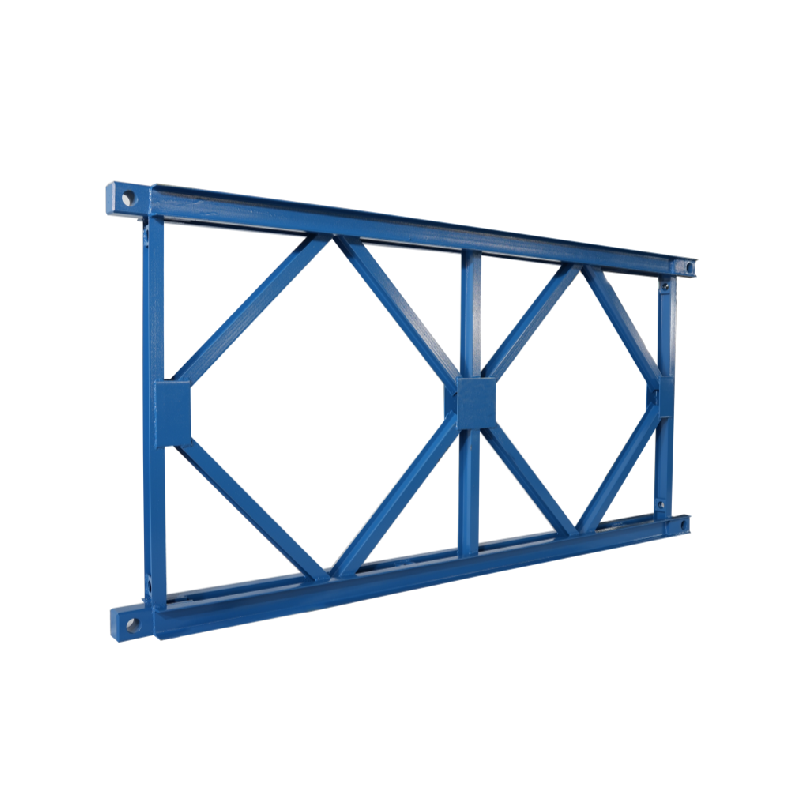
We must transition from historical blueprints to modern commercial variants. Current infrastructure procurement utilizes two primary bridge systems. Engineers evolved the original military concept into robust civilian solutions. You must understand the differences between these modern models. This ensures proper alignment for your specific project needs.
The SJ-200 Bailey Bridge remains closely related to the original 1941 design. It features the standard panel dimensions you expect. We consider it the versatile standard for general construction. It performs exceptionally well for medium-load requirements. You will frequently see it deployed for temporary highway detours. Rural infrastructure projects rely heavily on this model. Rapid emergency relief teams favor its straightforward assembly sequence.
However, you must acknowledge its structural limitations. The standard design may not meet the strictest deflection criteria. Ultra-heavy modern industrial loads can stress the standard pins over long spans. If you operate massive mining dump trucks, this model might experience excessive fatigue. You should limit its use to standard commercial traffic.
The SJ-321 Bailey Bridge represents the high-capacity evolution of modular engineering. This variant features noticeably wider panels. It utilizes much thicker chord members. Engineers designed an alternative pin structure for this model. These upgrades allow the system to resist much higher shear forces. We strongly recommend it for heavy-duty commercial applications.
Mining transport routes frequently utilize this robust system. It easily achieves permanent highway load compliance. You can meet strict HL-93 or HA/HB load standards using this structure. The added weight of the components requires slightly more lifting power. However, the resulting structural stiffness justifies the extra effort.
We want to guide you on choosing between the two systems. You must evaluate your required clear span first. Next, identify your target load class accurately. Finally, estimate your anticipated traffic frequency over the bridge's lifespan.
System Comparison Overview
Feature Category | SJ-200 Series | SJ-321 Series |
|---|---|---|
Load Capacity | Medium-Duty (Standard traffic) | Heavy-Duty (Mining/Industrial) |
Panel Dimensions | Standard width and chord thickness | Wider panels, thicker chords |
Primary Use Case | Temporary detours, rural access | Permanent highways, haul routes |
Compliance Targeting | General local traffic loads | HL-93, HA/HB standards |
You need an objective lens when evaluating modern modular systems. Selecting a supplier requires strict attention to engineering details. A bridge looks simple on paper. In reality, material quality dictates safety and longevity. We provide a framework for evaluating these critical systems.
Material and compliance standards require absolute transparency. You must demand clear documentation detailing the steel grades used. Modern modular bridges should utilize Q345B or Q355 high-strength structural steel. Lower grades compromise the entire truss geometry. You must also verify the applied anti-corrosion treatments. Standard environments usually require hot-dip galvanizing. Coastal areas demand specialized marine coatings. Saltwater exposure degrades untreated steel rapidly. You should specify the micron thickness of the galvanization layer before finalizing contracts.
Engineering certifications protect your project liability. You cannot rely on a supplier's internal promises alone. Highlight the necessity of independent structural calculations. You should request detailed fatigue life estimates from the manufacturer. Ensure the system demonstrates strict compliance with AASHTO guidelines. European projects must align with Eurocode specifications. Local bridge design rules often supersede international guidelines. Thorough documentation proves structural integrity. It also accelerates your permitting process.
Theoretical modularity looks perfect in a brochure. Real-world construction presents different challenges. You must understand field experience realities. We want to discuss what actually happens when deploying these bridges. Recognizing friction points early prevents costly delays.
Site preparation carries massive risks. You cannot overlook the absolute necessity of stable abutments. Accurate soil bearing capacity tests must happen before delivery. A modular bridge transfers immense point loads to its resting places. It will fail if the foundation is compromised. You must pour properly reinforced concrete abutments. The bank seats must remain perfectly level. Uneven settling causes dangerous torsional stress across the steel panels.
Assembly teams rarely use cranes over the water. Instead, they use the cantilever launch method. This historical process remains standard practice today. Teams build the bridge on dry land. They push the structure over specialized rollers. They attach a lightweight "launching nose" to the front. The nose crosses the gap first. It lands safely on the far bank rollers. Then, teams pull the heavier main span across. This ingenious method requires minimal heavy equipment.
You must monitor common implementation errors carefully. Field crews often rush the assembly phase. We compiled a list of common assembly pitfalls to watch for:
Misaligned Pins: Forcing panel pins into place damages the steel tolerances. Pins must slide smoothly.
Improper Torque: Failing to apply proper torque on transom bolts allows the bridge deck to rattle. This accelerates structural fatigue.
Counterweight Neglect: Teams often fail to account for counterweight safety during the launch phase. You must calculate the tipping point accurately.
Roller Jamming: Using damaged launch rollers causes the bridge to stall mid-air. You should always inspect bearings before pushing.
We urge you to hire an experienced launching supervisor. They understand how to read structural tension during the push. Their expertise prevents catastrophic drops. Correcting a jammed bridge over a river wastes days of labor.
The bailey bridge originated as a brilliant WWII logistical triumph. However, its core principles define modern rapid-deployment infrastructure today. Modularity, standardization, and simple assembly remain incredibly valuable concepts. These principles allow communities to reconnect quickly after natural disasters. They help construction firms maintain traffic flow during major repairs.
Your success today relies entirely on proper decision alignment. You must match the right modern system to exact site parameters. The lighter SJ-200 works perfectly for temporary rural access. The heavy-duty SJ-321 handles massive industrial loads effectively. Choosing the wrong variant leads to structural failure or wasted budgets.
We encourage you to take immediate next steps. Consolidate your required span lengths and load capacity demands. Gather comprehensive environmental data regarding soil and weather exposure. Once you organize this information, request formal structural drawings. Seek detailed procurement quotes from certified bridge engineers. Proper planning ensures a seamless deployment.
A: Conceptually yes, but structurally updated. Modern variants use advanced high-yield steel and improved hot-dip galvanization. Engineers modified panel dimensions in variants like the SJ-321 to meet current commercial load codes. The historical pinned-truss geometry remains identical.
A: It depends heavily on usage. Differentiate between temporary deployments lasting a few months and permanent installations. A properly maintained permanent structure lasts 50 to 75 years. This longevity depends strictly on fatigue loading limits and the quality of ongoing anti-corrosion maintenance.
A: Yes. This highlights the ultimate modularity advantage. You can swap out individual panels or transoms easily. You do not need to dismantle the entire bridge structure. This surgical replacement minimizes traffic downtime and lowers long-term repair expenses.


