
English 

Views: 0 Author: Site Editor Publish Time: 2026-09-23 Origin: Site


Miscalculating bridge load capacity risks catastrophic failure. It causes project delays and severe compliance violations. Buyers cannot rely on a single "maximum weight" metric. Modular bridge capacities are highly dynamic. A modular bailey bridge's true weight limit is determined by a complex matrix. We must evaluate span length, truss configuration, and component reinforcement simultaneously. This guide provides an objective, engineering-based framework. You can use it to determine exact load limits accurately. It helps project managers evaluate structural requirements thoroughly before procurement. We will break down exactly how different operational forces dictate safe tonnage. You will learn how to match your fleet requirements to the correct structural configuration.
Load capacity and bridge span share an inverse relationship; longer spans require complex configurations to maintain high tonnage limits.
Standard configurations typically support 20 to 40 tons, while a High Load Capacity Bailey Bridge can be engineered to exceed 80 tons.
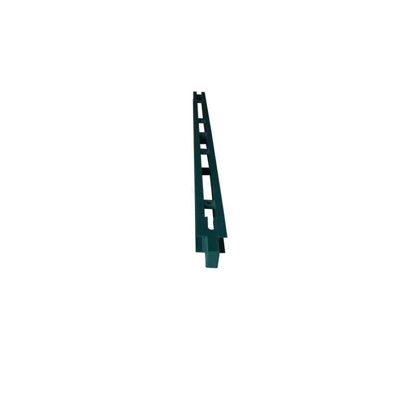
Integrating a Bailey Bridge Reinforced Chord significantly increases the bending moment and shear capacity for heavy commercial and industrial equipment.
Accurate procurement requires evaluating axle loads and dynamic impact factors, not just gross vehicle weight.
Every structural engineer understands one fundamental rule. Load capacity and clear span share a strict inverse relationship. As you increase the clear span of the bridge, you must add more steel panels. This extra steel significantly increases the dead load. Dead load refers to the self-weight of the bridge itself. A higher dead load leaves less available capacity for the live load. Live load represents the crossing vehicles and equipment. You must balance this equation carefully to achieve your target capacity.
Engineers manage this balance using specific truss assemblies. The industry uses standard nomenclature to define panel configurations. A Single-Single (SS) design uses one row of panels built one tier high. A Double-Single (DS) setup uses two rows of panels at a single height. A Double-Double (DD) configuration stacks two rows into two vertical tiers. For extreme spans, engineers specify Triple-Double (TD) or Triple-Triple (TT) layouts. These complex configurations add crucial stiffness to the structure.
You must also account for different structural forces. Specific points on the bridge experience entirely different stresses. The center span faces maximum bending moments. Bending forces try to sag or snap the middle of the structure. Conversely, the bridge ends face maximum shear forces. Shear forces attempt to slice through the connection pins where the bridge meets the abutments. Your chosen configuration must resist both bending at the center and shear at the ends.
Engineers categorize these structures into distinct performance tiers based on anticipated traffic. The standard capacity tier typically supports 20 to 40 tons. We see these bridges utilized for light civilian traffic. They support standard supply trucks and provide temporary rural access. The structural baseline relies on unreinforced single or double-truss designs. They are fast to assemble. They require minimal heavy lifting equipment. However, they cannot sustain continuous industrial hauling.
Industrial projects demand vastly superior strength. Mining operations and heavy logging sites require specialized equipment. You might need to move multi-axle dump trucks or specialized military logistics vehicles. These applications require a true High Load Capacity Bailey Bridge. These structures easily exceed 80 tons in safe working loads. Engineers achieve this by utilizing Triple-Triple (TT) or Quad-truss configurations. A reliable Heavy Duty Bailey Bridge uses multiple rows of steel to distribute massive point loads.
Upgrading capacity does not always mean adding more full-size panels. You can implement targeted reinforcements instead. Adding a Bailey Bridge Reinforced Chord fundamentally changes the structural math. You bolt these heavy steel chords directly to the top and bottom edges of the truss panels. This drastically improves the section modulus. It strengthens the areas most vulnerable to bending forces. The outcome is highly efficient. It allows for higher load classes without adding extra rows of heavy panels. This approach optimizes transport logistics and accelerates assembly time.
Table: Comparison of Common Truss Configurations and Typical Load Ranges
Configuration Type | Abbreviation | Primary Use Case | Relative Load Capacity |
|---|---|---|---|
Single-Single | SS | Pedestrian, Light Vehicles | Low (up to 15T) |
Double-Single | DS | Standard Supply Trucks | Medium (20T - 40T) |
Double-Double | DD | Commercial Freight | High (40T - 60T) |
Triple-Double (Reinforced) | TDR | Heavy Mining Equipment | Extreme (80T+) |
Generic tonnage claims mean nothing without standardized engineering frameworks. The original performance benchmark is the Military Load Classification (MLC) system. The MLC standard differentiates clearly between tracked vehicles and wheeled vehicles. Tracked vehicles like dozers distribute their weight evenly across a large surface area. Wheeled trucks concentrate massive forces directly onto tiny contact patches. An MLC 80 tracked rating does not automatically guarantee an MLC 80 wheeled rating. You must check both numbers.
Civilian engineering uses entirely different frameworks. You must map the modular capacity to modern highway standards. In North America, structural engineers rely on the AASHTO HL-93 load model. This standard accounts for a design truck combined with a uniform lane load. In Europe, engineers utilize Eurocode standard load models. These civilian standards mandate higher safety factors than military field manuals. They account for continuous daily civilian traffic rather than temporary emergency access.
Procurement teams must demand authoritative validation. Do not accept a simple sales brochure as proof of capacity. Highlight the necessity of requesting third-party finite element analysis (FEA). The manufacturer must provide FEA reports matching your specific span and configuration. Furthermore, request physical load test certifications. These documents prove the steel components meet strict yield strength requirements. Validated testing separates robust engineering from unsafe guesswork.
Static weight only tells half the story. Moving vehicles exert significantly more force than stationary ones. Engineers call this the Dynamic Impact Factor or impact allowance. When a heavy truck brakes sharply, it transfers massive horizontal forces into the deck. Acceleration creates similar stresses. Speed requires a strict safety multiplier. Engineers often add 15% to 30% above the static weight to calculate the true dynamic load. You must enforce speed limits to control these unseen forces.
Gross vehicle weight (GVW) creates a dangerous myth in bridge planning. Axle load distribution dictates the actual stress on the deck. A 60-ton vehicle spread across six axles may cross safely. It distributes the weight over a long section of the span. Conversely, a 40-ton vehicle resting on only two axles creates concentrated point loads. These point loads can punch through standard steel decking. You must evaluate the maximum single axle load of your heaviest equipment.
High-cycle environments introduce the risk of structural fatigue. Frequent haul roads face thousands of crossings per month. Steel flexes slightly under every passing truck. Over time, this microscopic flexing causes material degradation. Regular inspection dictates the long-term safe load limit. You must establish a proactive maintenance routine.
Best Practices for Bridge Inspection:
Inspect primary shear pins monthly for signs of deformation or cracking.
Check all transom clamps to ensure they maintain proper torque specifications.
Monitor steel deck plates for excessive deflection or weld fatigue.
Look for rust scaling around the bottom chords where moisture accumulates.
Specifying the right configuration requires rigorous data collection. Do not ask a manufacturer "how much a bridge costs" without providing technical parameters. You must supply a detailed operational profile. This prevents dangerous under-engineering. It also prevents wasteful over-engineering.
Required Data Gathering Checklist:
Exact clear span required: Measure the gap between the solid abutment resting points, not just the river width.
Maximum GVW and maximum single axle load: Provide the exact specs of your heaviest loaded vehicle.
Traffic volume and lifespan: Estimate the number of daily crossings and the intended years of use.
Site-specific environmental loads: Detail local wind speeds, snow accumulation risks, and seismic activity zones.
Buyers must navigate cost versus capacity trade-offs carefully. A standard double-single bridge handles immediate light traffic easily. However, your project might scale up next year. Upgrading an installed bridge disrupts operations. Sometimes, it makes sense to over-engineer the initial structure for future-proofing. Selecting a wider, higher-capacity layout now optimizes your future operational capabilities. Evaluate your project phases carefully to optimize your immediate budget constraints against future expansion needs.
Your next step requires professional consultation. Advise your team to initiate a preliminary site assessment. Have a geotechnical engineer survey the abutment soil. Then, request a customized load-span chart from the manufacturer. This chart must reflect your specific operational parameters. It will show you exactly which truss configurations safely support your fleet across your specific gap.
A modular bridge is never a one-size-fits-all product. Its true weight capacity represents a highly precise engineered calculation. You must balance the required clear span, the selected truss configuration, and specific steel reinforcements. Relying solely on gross vehicle weight invites structural failure. You must account for axle distributions, dynamic impact forces, and long-term fatigue.
We encourage project buyers to move past generic tonnage claims. Gather your exact fleet specifications and environmental data. Consult with qualified structural engineers to run a specific load-case scenario for your exact equipment fleet. Professional finite element analysis guarantees both operational safety and strict regulatory compliance.
A: Yes, it can support a 40-ton dump truck, but it depends strictly on the span length. A short span might handle it using a simple Double-Single layout. Longer spans require a reinforced Double-Single or a heavier Double-Double configuration to prevent dangerous sagging under the load.
A: Exceeding load limits pushes the steel past its safe yield limits. You risk permanent deck deformation and catastrophic shear pin failure. Overloading compromises the structural integrity immediately. Furthermore, unauthorized overloading instantly voids manufacturer warranties and violates local safety compliance laws.
A: It adds some individual component weight and requires extra bolting time. However, it often requires fewer overall truss panels than unreinforced high-capacity configurations. You avoid stacking third tiers or triple rows. This usually results in a net-neutral or significantly faster launching process.


