
English 

Views: 0 Author: Site Editor Publish Time: 2026-09-08 Origin: Site


Bridge infrastructure failures demand rapid solutions. Project access bottlenecks also require immediate, reliable interventions. Historically rooted in military engineering, the modern modular system remains a leading choice. We see it used constantly for temporary detours and disaster relief. We also see it deployed for permanent rural access. For civil contractors and project engineers, choosing a temporary system involves balancing numerous factors. You must weigh load-bearing requirements against span length. You must balance assembly speed against challenging site constraints. A lack of heavy crane access often complicates these engineering decisions. Understanding exactly how this structure distributes weight is absolutely critical. You must grasp how its modular components interact under stress. This deep knowledge helps you evaluate structural solutions confidently. It determines whether the system meets your project's operational demands. Furthermore, it clarifies how the system achieves strict regulatory compliance standards. We will explore the core mechanics and stabilizing components below. We will also review installation methods to guide your next infrastructure project.
Modular Load Distribution: The system relies on a pin-jointed truss design that efficiently transfers bending and shear forces, allowing lightweight parts to support heavy commercial loads.
Scalable Strength: Load capacity and span length are highly customizable by adding or stacking standardized panels (e.g., from Single-Single to Triple-Double configurations).
No-Crane Assembly: The ingenious "cantilever launching" method allows the bridge to be pushed across a gap from one side, drastically reducing heavy equipment requirements.
Standardized Components: Core elements like the Bailey Bridge Panel, Transom, and bracing systems ensure rapid deployment and simplified quality control.
Let us discuss the fundamental engineering framework. The system operates as a pre-fabricated, pin-jointed lattice truss. It utilizes basic geometric principles to support immense weight. Engineers design the framework around a series of interconnected triangles. Triangles provide exceptional rigidity. They resist distortion under intense pressure. This geometry distributes forces evenly across multiple small steel elements. Force distribution dictates how the bridge manages operational stresses. The side panels act as the main load-bearing walls. They feature distinct top and bottom chords. These chords handle the primary bending moments. When a heavy vehicle drives across, it pushes the deck down. This action creates tension along the bottom chords. It simultaneously creates compression along the top chords. Meanwhile, the internal vertical and diagonal webbing handles the shear forces. The webbing prevents the panels from buckling or twisting under active traffic loads. This highly efficient distribution of forces delivers a major business outcome. No single steel component is unmanageable. A small crew can lift the individual parts manually. A light forklift can move heavier beams easily. You drastically reduce mobilization and logistics costs. You also shrink setup timelines compared to conventional concrete construction. You avoid the need for heavy steel beam bridges entirely. The reliance on clever physics over sheer mass makes this approach incredibly practical. It allows remote deployments where heavy machinery simply cannot reach.
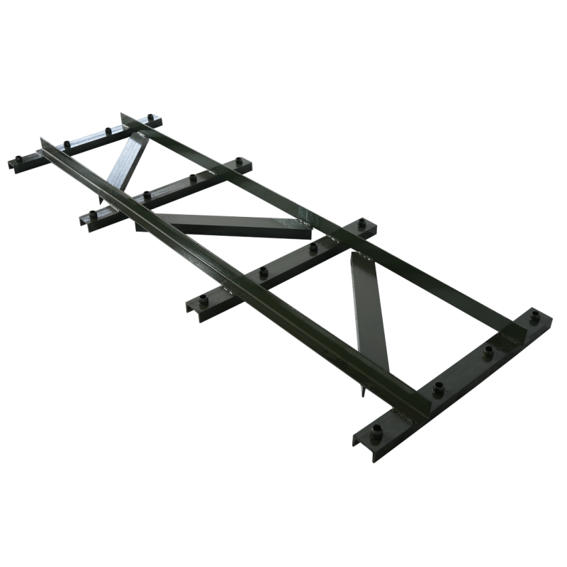
Every robust structure relies on high-quality standardized parts. You must understand how these elements interact. They create structural integrity. They ensure full compliance with global safety standards. Let us break down the primary structural elements. The Bailey Bridge Panel serves as the fundamental building block. It is a 10-foot welded steel lattice panel. It acts as the primary load-bearing truss for the entire structure. Workers pin these panels together end-to-end. This simple connection forms continuous bridge girders stretching across the gap. You can easily replace a single damaged panel without dismantling the whole structure. Next, we look at the crucial cross-girders. The Bailey Bridge Transom consists of heavy steel I-beams. These beams rest securely on the bottom chords of the main side panels. They span the entire width of the structure. They directly support the road deck above. Crucially, they transfer the live traffic load outward into the side truss panels. Beneath these transoms lies another vital element. The Bailey Bridge Horizontal Brace acts as the critical sway bracing system. Installers bolt these braces beneath the transoms in a crisscross pattern. This provides essential lateral rigidity. It prevents the bridge from twisting under heavy, asymmetric loads. It also protects the structural frame from high wind pressures in exposed valleys. Finally, decking and pins finalize the functional roadway. High-tensile steel panel pins lock the entire system together. You do not need any field welding. This eliminates the need for specialized welders on site. You can choose different decking options based on traction needs. Anti-skid steel plates offer maximum durability for industrial traffic. Timber decks provide a lighter, cost-effective alternative for rural community access.
Engineers must evaluate project requirements carefully. They determine the required bridge strength using established evaluation criteria. Scalability relies entirely on standardized configurations. You avoid all custom manufacturing delays. You simply combine existing parts to increase overall capacity. Engineers stack panels vertically or place them side-by-side. Let us outline the standard industry naming convention. Engineers label setups based on "Panels wide x Panels high."
Table: Standard Modular Configurations and Load Applications
Configuration Name | Abbreviation | Panel Layout Structure | Best Project Application |
|---|---|---|---|
Single-Single | SS | 1 panel wide, 1 panel high | Short spans, pedestrian access, light vehicles. |
Double-Single | DS | 2 panels wide, 1 panel high | Medium spans, standard commercial traffic. |
Double-Double | DD | 2 panels wide, 2 panels high | Longer spans, heavy commercial trucks. |
Triple-Double | TD | 3 panels wide, 2 panels high | Extreme spans, heavy-haul industrial equipment. |
Single-Single (SS) fits short gaps perfectly. You use it primarily for light vehicle access. It installs rapidly. Double-Single (DS) and Double-Double (DD) represent the industry standard for most highways. They handle heavy commercial trucks easily. They support much longer spans safely. Triple-Double (TD) and beyond support extreme structural demands. You use these heavy-duty configurations for heavy-haul industrial equipment. Mining excavators and logging trucks require this level of reinforcement. Modern configurations adhere strictly to authoritative standards. Civil engineers analyze them to meet specific highway load ratings. This includes the AASHTO HL-93 standard in North America. It also meets rigorous Eurocode equivalents across Europe. This testing ensures full regulatory compliance for public use. You can trust this scalability model completely. It removes the guesswork from temporary bridge engineering.
A major operational advantage addresses a common buyer question. How do we install this over a rushing river without a crane on the opposite bank? The cantilever launch method solves this exact logistical nightmare. You build everything on one side of the gap. You push the structure across the void manually or mechanically. Here is the step-by-step rollout process:
Assembly on Rollers: The construction crew builds the bridge on the near bank. They assemble the panels on heavy-duty launching rollers positioned carefully on the ground.
The Launching Nose: Workers attach a lightweight, upward-tilted skeleton frame to the front. We call this the launching nose. It reaches the far bank first to establish a resting point.
Pushing the Bridge: Using a light vehicle, excavators, or heavy-duty winches, the team pushes the structure. It slowly moves outward over the gap in controlled increments.
Counterweighting: The crew temporarily adds extra panels to the rear of the structure. This acts as a vital counterweight. It prevents the bridge from tipping forward into the gap before the nose lands.
Jacking Down: Once the nose crosses the gap, the team removes it. They jack the entire bridge down off the temporary rollers. It finally rests on permanent steel bearings fixed to the abutments.
Risk mitigation remains crucial during this launching process. You need stable, well-engineered abutments on both sides. The launching rollers carry immense point loads during the push. Soft soil can cause the rollers to sink or shift. Strict adherence to launching weight calculations is absolutely mandatory. If the rear counterweight fails, the entire structure could plunge into the river. Engineers must supervise the launch closely. They ensure absolute safety and structural alignment throughout the maneuver.
When should you select a bailey bridge for your site? It is ideal for rapid emergency replacements following severe floods. It serves perfectly as a temporary haul road for mining or logging operations. Remote project locations often suffer from limited logistics access. These sites benefit immensely from this easily transportable modular system. However, we must discuss transparent limitations. Skeptical buyers and cautious engineers need the full picture before committing.
Fatigue Life: These are highly durable steel structures. Yet, pinned joints in temporary bridges require regular visual inspection for wear. This is especially true if you use them in high-volume, permanent highway applications.
Speed Limits: Traffic speeds are generally restricted on these structures. The modular steel deck can generate significant noise under fast-moving tires. High speeds also cause excessive structural vibration. You must enforce clear speed limits.
Clearance Issues: Multi-story configurations create internal overhead or width restrictions. A Double-Double setup includes stacked panels extending vertically. You must cross-check these dimensions carefully against expected commercial vehicle sizes.
Take decisive action on your next step. Advise your decision-makers to conduct a thorough site survey immediately. Focus heavily on measuring the exact gap length. Calculate the maximum anticipated vehicle weight your project requires. Test the abutment soil conditions rigorously using geotechnical methods. Gather all this data before requesting an engineering configuration quote. Clear, accurate data prevents costly redesigns and ensures a perfectly matched structural solution.
The working principle of this modular system marries simple physics with standardized manufacturing. It solves complex logistical access problems in challenging environments worldwide. You achieve massive load-bearing capacity without needing massive lifting equipment. The ingenious pin-jointed truss mechanics distribute stress perfectly across the frame. Scalable panel configurations adapt instantly to your changing project demands. Consult with qualified structural engineers for your next planning phase. They can calculate the exact panel configuration you need for your anticipated loads. They will determine proper transom spacing based on your heaviest site vehicles. They will also design robust abutments tailored to your specific soil conditions. Proper planning ensures a swift, compliant, and highly safe installation.
A: Varies by configuration and load, but typically practical up to 200 feet / 60 meters without intermediate piers, though longer spans are achievable with advanced configurations or supports.
A: Yes, by upgrading to Double-Double or Triple-Double configurations, they can be rated for heavy-haul trucks and excavators.
A: Depending on the span, crew size, and site prep, a standard bridge can often be launched and operational in 3 to 7 days.
A: While designed as temporary structures, with proper anti-corrosion treatments (galvanization) and regular maintenance, many serve safely as permanent bridges for decades.


