
English 

Views: 0 Author: Site Editor Publish Time: 2026-09-30 Origin: Site


Procurement teams and site engineers face incredibly high stakes when specifying a temporary or permanent bailey bridge for critical infrastructure projects. Choosing the wrong structural configuration can quickly lead to costly clearance failures. You might also face severe traffic bottlenecks or compromised worker safety on site. Both “Through” and “Deck” setups rely on the exact same proven, modular engineering principles. However, placing the roadway deck differently relative to the load-bearing trusses fundamentally alters the outcome. It changes the structural capabilities, available assembly methods, and ideal use cases. We created this comprehensive guide to help you compare these options both technically and commercially. You will learn to properly evaluate physical site constraints. We will explore how to assess strict operational limits and maintenance demands before finalizing your procurement. Understanding these critical differences ensures your project stays firmly on schedule and functions safely for its intended lifespan.
Through Bridges place the roadway between the trusses, maximizing under-bridge clearance but strictly limiting vehicle width.
Deck Bridges place the roadway on top of the trusses, accommodating wide or multi-lane traffic, but require substantial clearance beneath the structure.
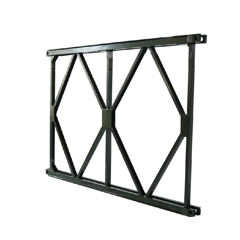
Component selection—specifically the interplay between the Bailey Bridge Truss Panel and the Bailey Bridge Deck Panel—dictates total load capacity and deflection limits.
Maintenance and inspection costs differ significantly between the two designs due to accessibility.
Understanding the fundamental geometry of these structures is essential. The placement of the roadway dictates how the entire system bears weight and resists dynamic forces.
The Through configuration features a distinct geometric design. The roadway deck rests securely on the bottom chords of the main trusses. Vehicles essentially drive "through" the supporting steel corridor. The structural walls sit directly above the deck level. They naturally act as robust side rails or safety parapets. This built-in barrier protects vehicles from veering off the edge.
This design creates a highly efficient load transfer path. Traffic weight pushes down on the Bailey Bridge Deck Panel. The panels transfer this force to the lower transoms. These transoms then push the load outward into the vertical side trusses. Finally, the trusses carry the load toward the end abutments. This creates a highly stable, low-center-of-gravity structure.
The Deck configuration flips this geometry entirely. Here, the roadway rests squarely on the top chords of the trusses. Drivers see an open, unimpeded flat surface. The entire load-bearing truss structure remains hidden securely beneath the roadway.
In this setup, the Bailey Bridge Truss Panel acts entirely in compression and tension below the traffic line. It provides massive underlying support. Because the walls do not box in the roadway, engineers can design cantilevered deck extensions. You can widen the lanes far beyond the internal width of the supporting trusses beneath them.
You must evaluate physical site conditions before selecting a design. Environmental factors often eliminate one configuration immediately.
Deck bridges carry a significant physical constraint. They require deep abutments or massive vertical clearance below the crossing point. You must fit the entire truss structure beneath the deck. This makes them highly unsuitable for flood-prone rivers. High water events can carry large debris. Floating logs or ice can easily strike the under-slung trusses, causing catastrophic failure.
Through bridges offer a major environmental advantage here. They keep almost all the structural steel safely above the crossing gap. The deck forms the lowest point of the structure. This makes them ideal for shallow ravines, flat terrain, or rivers featuring high-water marks. The trusses remain completely safe from passing debris below.
Through bridges face a strict geometric constraint regarding width. The internal distance between the two solid truss walls physically restricts the roadway. Standard configurations usually accommodate only single-lane traffic. They are entirely unsuitable for oversized mining equipment or exceptionally wide commercial loads.
Deck bridges provide a massive advantage for traffic flow. They offer virtually unlimited roadway width. Because the trusses sit underneath, the deck can expand outward. This configuration easily supports multi-lane highway traffic. It also accommodates heavy industrial vehicles without any dangerous side-clearance risks.
Engineers must carefully evaluate how a Modular Steel Bailey Bridge distributes heavy, dynamic loads across different spans. Both configurations handle massive weight, but they deflect differently under stress.
Longer spans always require structural reinforcement. Engineers use multi-truss or multi-story panel configurations based on the required span length. Through bridges naturally resist lateral sway well because the high walls brace the structure. Deck bridges often require complex cross-bracing underneath to prevent dangerous lateral deflection under heavy, asymmetrical loads.
Configuration | Primary Load Path | Deflection Control Strategy | Reinforcement Method |
|---|---|---|---|
Through Bridge | Deck → Transom → Bottom Chord → Trusses | Overhead sway braces & side structural framing | Adding exterior panel rows (Double/Triple Truss) |
Deck Bridge | Deck → Top Chord → Internal Truss Web | Under-deck lateral bracing & heavy transoms | Adding deeper lower panel stories (Double Story) |
Building these structures requires careful logistical planning. The configuration dictates the necessary earthworks and the required lifting equipment.
You must contrast the abutment requirements closely. Deck bridges inherently demand a larger earthwork footprint. They often require deeper excavations to sink the trusses. Alternatively, you must build much higher approach ramps to align the incoming roadway smoothly with the elevated top chord. This increases initial civil engineering costs.
Through bridges require minimal approach adjustments. The deck sits low, aligning easily with existing flat roadways. This reduces excavation time and heavy machinery requirements at the deployment site.
The cantilever launching process is a hallmark of modular steel construction. Through bridges are generally much easier to launch across a gap. They have a naturally lower center of gravity. Construction crews can easily push them over standard rollers using launching noses. The risk of lateral tipping remains minimal during a standard push.
Deck bridges present higher erection risks over deep gaps. Launching them is precarious due to their top-heavy nature once the deck is applied. Often, crews must assemble them in place. This setup highlights severe tipping risks. It often requires heavy crane positioning to assemble the bridge over a deep gorge safely.
Handling heavy modular components in constrained staging areas presents serious safety risks. You must follow strict protocols when erecting either design.
Ensure the staging ground is perfectly level before assembling the launching nose.
Restrict personnel from standing in the blind spots of crane operators during panel positioning.
Install all temporary sway braces immediately before pushing the structure over the rollers.
Monitor the counterweight balance continuously during a cantilever launch to prevent sudden tipping.
Accessibility changes everything for maintenance crews. You must plan for ongoing operational expenses based on the structural geometry.
We must evaluate inspection access skeptically. Through bridges offer a distinct advantage here. They allow incredibly easy visual inspection of the primary load-bearing trusses. Inspectors can walk safely along the pedestrian or vehicle deck. They can check pins, chords, and vertical panels directly from the roadway without special equipment.
Deck bridges hide their critical infrastructure. They require under-bridge inspection units, commonly known as snooper trucks. In deep valleys, crews might need to build temporary suspended scaffolding. They must physically reach underneath to check pins, lower chords, and transoms. This heavily increases your long-term operational expenditure (OpEx).
You must discuss the harsh realities of component replacement. Replacing a damaged deck panel on a Through bridge is straightforward. Crews can lift the damaged panel straight up and drop a new one into the transom slots. The trusses remain completely undisturbed.
Replacing components on a Deck bridge can be more complex, depending on the connections. You must also examine their susceptibility to corrosion. Deck bridges suffer from under-deck condensation. Moisture traps easily against the upper chords hidden by the roadway. Through bridges expose their trusses to open air. This open exposure allows wind to dry the steel quickly, generally reducing localized rust.
Selecting the right configuration is a matter of strict adherence to environmental geometry. Review these guidelines to finalize your approach.
You face strict vertical clearance limits below the bridge crossing.
Your project requires rapid, emergency deployment (military uses, disaster relief, temporary detours).
A standard highway width is completely sufficient for your expected traffic.
You lack the heavy lifting cranes needed for complex aerial assembly.
Your project has a distinct need for multiple lanes.
You expect oversized industrial transport, such as wide mining haul trucks.
You are crossing deep valleys or overpasses where under-bridge space is abundant.
You are building permanent or semi-permanent installations prioritizing traffic volume over installation speed.
Project Requirement | Recommended Configuration | Primary Reason |
|---|---|---|
Flash Flood Zone | Through Bridge | Keeps steel structure safely above debris impact zones. |
Dual-Lane Highway | Deck Bridge | Allows unlimited width expansion beyond standard truss dimensions. |
Emergency Detour | Through Bridge | Faster cantilever launch requires less site preparation. |
Deep Gorge Crossing | Deck Bridge | Abundant under-clearance allows hidden support structures. |
We strongly advise consulting with qualified structural engineers before finalizing procurement. They must perform a site-specific load rating analysis. You also need comprehensive geotechnical surveys of the abutment locations. These steps ensure your chosen configuration will perform safely under real-world stresses.
The choice between Through and Deck configurations is rarely a matter of simple aesthetic preference. It demands strict adherence to site geometry, clearance limitations, and expected traffic volume. You must balance the physical constraints of your crossing gap against the width requirements of your vehicles.
Both configurations effectively leverage the massive efficiency and strength of modular steel construction. However, they require vastly different approaches to abutment design, launching procedures, and lifecycle maintenance. Recognizing these operational differences early prevents costly delays and safety hazards.
We encourage project managers to request a customized site evaluation immediately. You should obtain a comprehensive technical data sheet matching your specific span and load class requirements. Reaching out for expert analysis guarantees a successful, resilient infrastructure deployment.
A: No. The width is permanently fixed by the horizontal transoms connecting the two main truss walls. Widening the roadway physically requires complete disassembly of the entire structure and a fundamental structural redesign using longer transoms.
A: Yes. Both configurations use standard modular panels, including chords, diagonals, and transoms. However, the assembly bracing, the sway braces, and the specific connection hardware differ greatly based on the chosen design.
A: The Through configuration is historically much faster to install. Crews can cantilever launch it quickly with minimal equipment. It also requires significantly less complex earthworks for the approach ramps, making it the global standard for emergency deployment.


