
English 

Views: 0 Author: Site Editor Publish Time: 2026-09-16 Origin: Site


Project managers and engineers often face tight deadlines for critical crossings. You need robust infrastructure deployed rapidly across challenging terrains. However, balancing fast deployment timelines against strict structural safety remains a complex challenge. Load compliance demands precise execution on every job site. A poor installation compromises worker safety and ruins your project schedules.
This guide solves those pressing operational problems. We provide a transparent, step-by-step breakdown of the entire assembly and disassembly process. You will learn how to accurately forecast labor requirements for your next crossing. We show you how to identify essential equipment and properly stage your components.
You will also understand component procurement needs much better. Our actionable insights ensure your crossing meets rigorous engineering standards. You can achieve this without unnecessary delays or structural risks. Follow this guide to master rapid bridge deployment and guarantee a safe, reliable span.
Proper site preparation and precise calculation of the launching nose are critical to prevent tipping during installation.
Procuring standardized, high-tolerance components directly impacts the speed of assembly and the safety of the final structure.
The cantilever launching method allows for installation without heavy cranes in the riverbed or gap.
Dismantling requires the same meticulous weight-balance calculations as installation to ensure component reusability and operational ROI.
You cannot build a strong structure on weak groundwork. Pre-installation logistics dictate the safety and speed of the entire rollout. Teams must address the physical environment before any steel arrives.
You must measure the exact span first. Teams must also test the soil bearing capacity at the abutments. Engineers often use standard penetration tests for accurate ground data. The ground handles massive dynamic launching loads. It supports the entire bridge weight acting on the launching rollers. A weak bank will collapse during the forward push.
You should also check for underground utilities or soft pockets. Ground improvement techniques become necessary if the soil fails preliminary tests. You might need to drive piles or pour concrete pads to stabilize the abutments permanently.
Establish a flat, compacted assembly area on the launching side. This area must match the combined length of the bridge plus the launching nose. Use heavy rollers to compact the dirt thoroughly. Lay gravel or steel plates if the soil feels soft or muddy.
Organize your parts arrival meticulously. Stack heavy panels near the assembly line. Keep smaller pins and bolts in secure, marked bins. Proper logistics prevent workers from searching for parts during critical assembly phases.
Shortlist your necessary tools early. Having the right machinery prevents dangerous delays. You rarely need massive cranes, but you do need specific launching gear.
Table: Essential Equipment for Cantilever Launching
Equipment Type | Primary Function | Recommended Quantity |
|---|---|---|
Rocking Rollers | Support heavy bridge weight during launch | 4 to 8 units (based on span) |
Plain Rollers | Guide the launching nose forward | 4 to 6 units |
Hydraulic Jacks | Lowering structure onto permanent bearings | Minimum 4 heavy-duty units |
Winches / Dozers | Pulling or pushing the assembled span | 1 to 2 units |
Light Crane or Excavator | Lifting panels onto the assembly line | 1 unit |
Define a successful rollout clearly. Base your success on alignment accuracy first. A few millimeters off at the start becomes a massive deviation at the gap center. Zero safety incidents define a truly successful day. Finally, strict adherence to projected deployment timelines keeps the overall project moving forward.
A sturdy crossing requires high-quality, standardized components. Each piece plays a specific role in carrying loads and resisting environmental forces. Let us examine the vital parts.
These are your fundamental modular units. They handle immense bending moments under heavy traffic. Truss panels demand high-yield steel and exact pinhole tolerances. You cannot force panel pins into misaligned holes. Poor tolerances cause alignment compounding errors. Small errors grow as you add more panels to the span.
Standardized pins lock the panels together. They endure severe shear forces. You must inspect every pin for straightness before inserting it. Never use a hammer to force a tight pin. This practice damages the steel structure permanently.
You must secure the main structure properly. This requires vital Bailey Bridge Accessories. These include bracing frames, rakers, sway braces, and chord bolts. Bracing frames stop the panels from twisting under load. Rakers keep the side panels perfectly vertical.
Sway braces handle lateral wind loads efficiently. Sub-standard accessories compromise wind and sway resistance. They put the entire crossing at risk during severe storms. Always procure these accessories from certified manufacturers to guarantee structural integrity.
Evaluate your decking criteria carefully. You will choose between steel orthotropic plates or timber based on expected traffic. An optimal Bailey Bridge Deck Panel system meets HS20 or HL-93 load classes easily. Steel panels resist wear and tear better than timber.
The decking must also satisfy strict anti-skid requirements. Vehicles need safe traction during heavy rain or snow. Many modern steel panels feature an epoxy aggregate coating. Others use a raised chequered pattern. Secure the panels tightly to the transoms to prevent dangerous rattling under live traffic.
Consider the bridge ends closely. The Bailey Bridge End Post is absolutely essential. It transfers the total bridge load downwards. It moves the accumulated weight from the trusses to the bearings and baseplates at the abutments.
You cannot ignore its structural importance. The end post features specialized bearing blocks. These blocks accommodate slight rotational movements as the bridge deflects under heavy trucks. Proper installation of the end post ensures the abutment receives the load evenly.
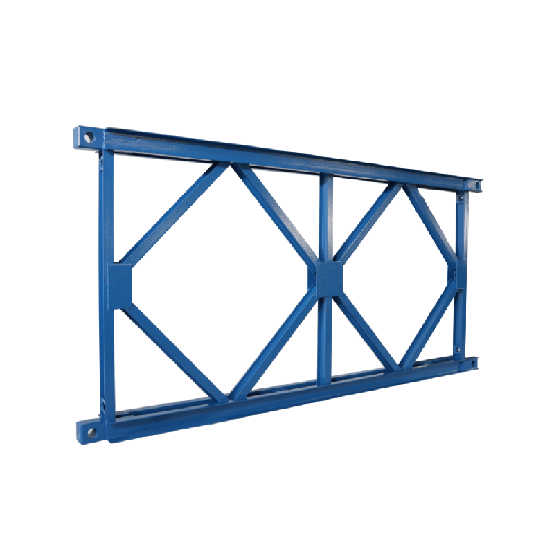
Proper execution prevents costly accidents. The cantilever launch method keeps workers out of the dangerous riverbed. Follow these structured steps for a flawless installation.
You must build the launching nose first. It acts as a lightweight guide for the main structure.
Assemble the lightweight front section of the bridge on the staging area.
Leave out the heavy steel deck panels on this nose section to reduce forward weight.
Design the nose to reach the far bank rollers before the center of gravity crosses the near bank.
Calculate the exact counterweight needed on the tail end.
Add extra truss panels to the rear if necessary. This prevents catastrophic tipping during the forward push.
Set up rocking rollers and plain rollers on both banks. Plain rollers guide the lighter launching nose initially. Rocking rollers handle the massive weight of the main bridge sections. They tilt slightly to accommodate the deflection of the trusses during the push.
You must align all rollers perfectly. Use a laser level to ensure they sit on exactly the same horizontal plane. Misaligned rollers create immense friction. They can cause the entire structure to jam mid-launch.
The launch requires patience and constant monitoring. Use heavy-duty winches, dozers, or even manual labor. Push the structure across the gap slowly. Keep the movement smooth and continuous.
Teams must monitor the center of gravity continuously. Stop the push immediately if the tail section begins to lift. A small miscalculation can cause sudden tipping. Have spotters on both banks communicating via two-way radios.
Watch the rollers closely. Ensure the bottom chords of the truss panels do not slip off the roller flanges. Apply grease to the rollers to minimize pushing resistance. Never rush this phase.
Receive the launching nose on the far bank plain rollers. Guide it carefully until it rests securely. Continue pushing until the main bridge spans the gap entirely. Stop the movement once the structure reaches its final position.
Dismantle the launching nose components piece by piece. Next, jack up the main span simultaneously on both banks. Use high-capacity hydraulic jacks. Remove the launching rollers from underneath the bottom chords. Finally, lower the structure slowly onto the end posts and permanent bearings.
Lay the transoms across the lower chords. Space them according to your engineering layout plans. Secure the deck panels firmly to the transoms. Use specialized decking clips or heavy-duty bolts.
Install the necessary curbs and guardrails to protect vehicles. Add run-on ramps at both ends for a smooth transition from the road surface. Conduct a final visual inspection of all bolts and pins before opening the crossing to traffic.
Taking down a modular structure requires just as much care as building it. Your goal is safe component recovery. Maximizing component lifespan improves project efficiency for future deployments.
You start by re-installing the launching nose. It acts as a necessary counterweight again. You cannot pull the bridge back safely without it. Next, jack the main span up off the permanent bearings. Place it back onto the plain and rocking rollers.
Use heavy-duty winches on the original staging bank. Pull the structure in reverse slowly. Keep the center of gravity balanced exactly as you did during the installation. Dismantle the rear sections panel by panel as they reach the staging area.
Evaluate all hardware carefully as you break it down. Check parts for shear stress, thread damage, or metal fatigue. Look for elongated pinholes on the truss panels. Discard any component that shows permanent deformation.
Clean off dirt, mud, and debris immediately. Re-grease every panel pin to prevent rust. Inventory your parts accurately. Proper storage maximizes the asset lifecycle. Stack panels upright on timber blocks to keep them off the damp ground.
Leave the site exactly as you found it. Ensure zero impact on the watercourse or surrounding terrain. Remove all temporary abutments, concrete pads, and staging areas carefully. Reseed the staging area if you compacted natural vegetation. Good environmental practices protect your company reputation and satisfy local regulations.
Industry standards govern modular infrastructure strictly. You must prioritize rigorous quality control to mitigate operational risks. Rely on proven engineering frameworks rather than guesswork.
You must conduct post-installation load testing. Verifying structural compliance is non-negotiable. Ensure your crossing meets AASHTO standards. Eurocode guidelines also provide excellent safety benchmarks. Real-world testing validates your theoretical calculations.
Engineers run heavy trucks across the span. They measure the deflection accurately using surveyor equipment. They check for unexpected settlement at the abutments. Document these test results carefully. They prove the bridge is safe for public or industrial use.
Avoid forcing misaligned panel pins. Hammering tight pins compromises structural integrity and damages the steel grain. Realign the panels instead of forcing the connection. Keep a heavy crowbar handy to adjust panel positions gently.
Furthermore, never miscalculate the cantilever balance point. A wrong calculation leads to catastrophic tipping. The bridge could fall into the river, destroying the components and risking lives. Always double-check your counterweight formulas before pushing.
Always adjust installation timelines for adverse weather. High winds affect the exposed launching nose dangerously. Stop the launch if wind speeds exceed safe operational limits. Rain makes the steel panels slippery and dangerous for workers.
Unstable muddy banks sink your rollers under heavy loads. Use thick steel plates to distribute the roller weight effectively. Monitor river levels if you are working near active currents. Flash floods can wash away temporary abutments before you finish the launch.
Your project success depends heavily on reliable manufacturing partners. Procuring a dependable bailey bridge demands diligent vetting. Never compromise on material quality to save upfront expenses.
Buyers must demand verifiable ISO certifications. A reliable factory maintains ISO 9001 quality management systems. Always request raw material test reports for every batch. These mill certificates prove the steel grade meets international requirements.
Traceable weld inspections guarantee structural soundness. Factories should use non-destructive testing (NDT) on critical welds. Ultrasonic testing reveals hidden flaws inside the steel. Reject suppliers who cannot provide these basic quality assurance documents.
Ensure new parts seamlessly integrate with standard modular systems. They must fit your existing OEM inventory perfectly. Standardized dimensions prevent frustrating mid-assembly delays. Ask the supplier if their panels conform to standard 3.048-meter lengths.
Select partners who provide comprehensive technical support. They should offer detailed design sketches tailored to your specific gap. They must supply precise 3D layout plans for the launching phase.
Good partners provide on-site engineering advisory during your first installation. An experienced supervisor catches alignment mistakes early. They teach your crew the nuances of cantilever launching safely.
Procurement teams must act smartly. Request specific load-capacity calculations based on your actual traffic needs. Ask for comprehensive shipping logistics quotes to your remote site. Avoid relying on generic price lists that hide shipping or accessory costs.
The modular ingenuity of these structures relies heavily on precise execution. High-quality manufacturing makes rapid deployment possible, even in remote locations. When teams follow strict site preparation and meticulous cantilever formulas, installations proceed safely and efficiently.
Prioritize structural safety and component durability over the lowest initial bid. This approach ensures long-term usability and project success. Contact our engineering team today. We offer site-specific consultations, precise load calculations, and detailed quotes for your bridge components.
A: Installation timelines depend on span length, crew size, and available equipment. A standard 30-meter span takes a trained crew of six about three to five days using light machinery. Manual launches take slightly longer but remain highly efficient for remote areas.
A: No. The cantilever roller method bypasses the need for heavy cranes. You assemble the structure on one bank and push it across using rollers, a lightweight launching nose, and simple winches or dozers.
A: You can dismantle and reuse these steel components dozens of times over many decades. However, post-dismantle inspection is critical. You must check for metal fatigue, re-grease pins, and replace damaged hardware to maintain optimal safety.
A: Yes. You can install them safely over active water currents. Since the cantilever launch happens entirely from the banks, no equipment or personnel needs to enter the water. You only need secure, stable abutments on both sides.


